Boundary Conditions
Boundary conditions specify how the system under investigation (referred to as "Slab" for the case of interfaces) can interact or is related to its surroundings. Such customization of boundary conditions can be especially resourceful in the case of Effective Screening Medium calculations.
Set Boundary Conditions Dialog
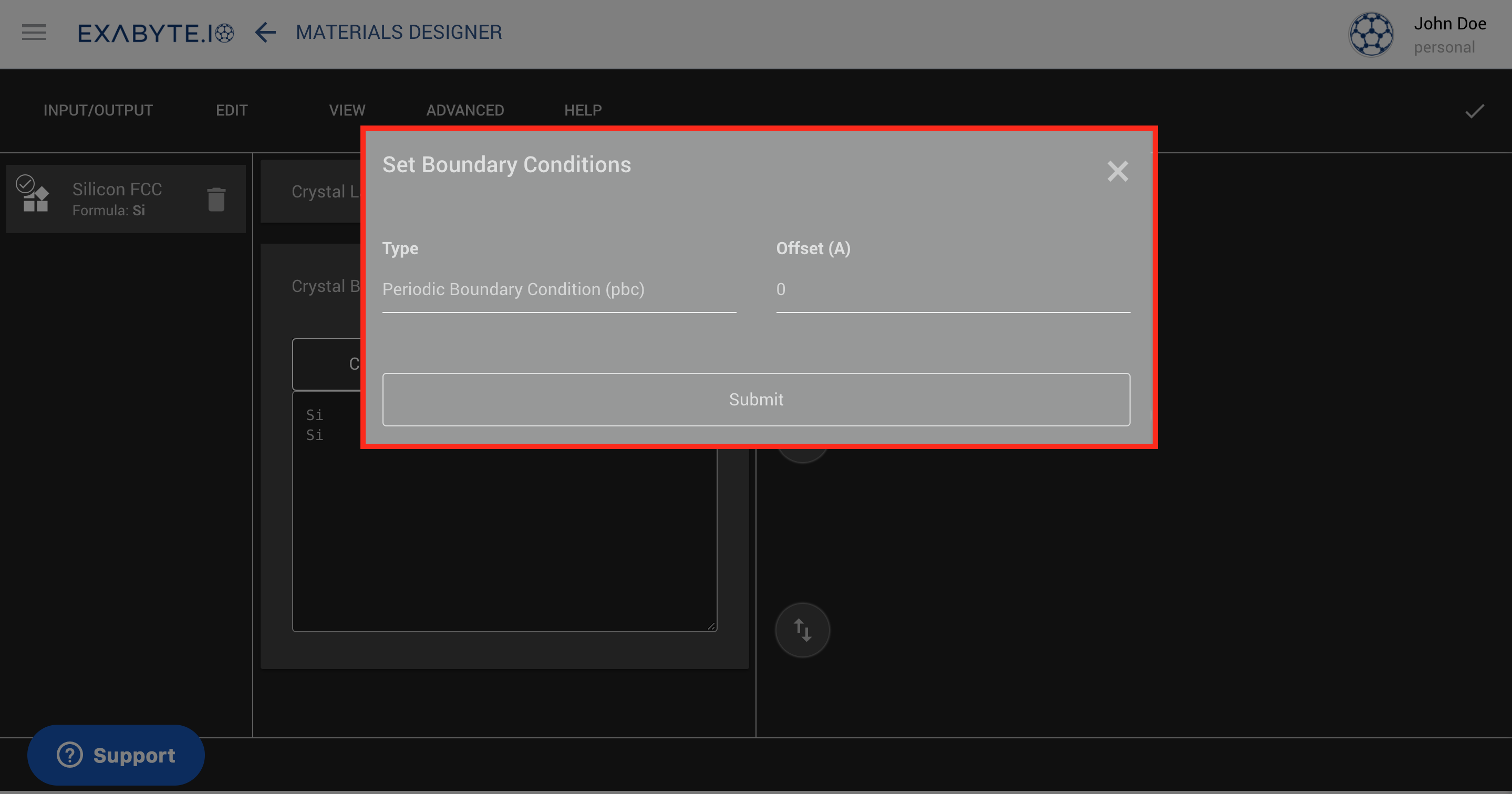
Open the "Set Boundary Conditions" dialog via the "Advanced" menu within the Materials Designer interface. The dialog has the appearance as highlighted in the image below.

Boundary Conditions Types
The dialog features a drop down menu on the left, where the type of boundary condition can be chosen and applied perpendicularly to the central slab under consideration. We offer the possibility to choose between the following distinct types, which are also reviewed in Ref. [7] cited in this page:
- Periodic Boundary Conditions (pbc): the system is completely surrounded by identical replicas of itself in all three dimensions 1.
- Vacuum-Slab-Vacuum (bc1): immerse the slab between two semi-infinite vacuum regions.
- Metal-Slab-Metal (bc2): immerse the slab between two semi-infinite metallic electrodes, with optional fixed electric field applied between them.
- Vacuum-Slab-Metal (bc3): immerse the slab between one semi-infinite vacuum region (left-hand side) and one semi-infinite metallic electrode (right-hand side).
Coloring
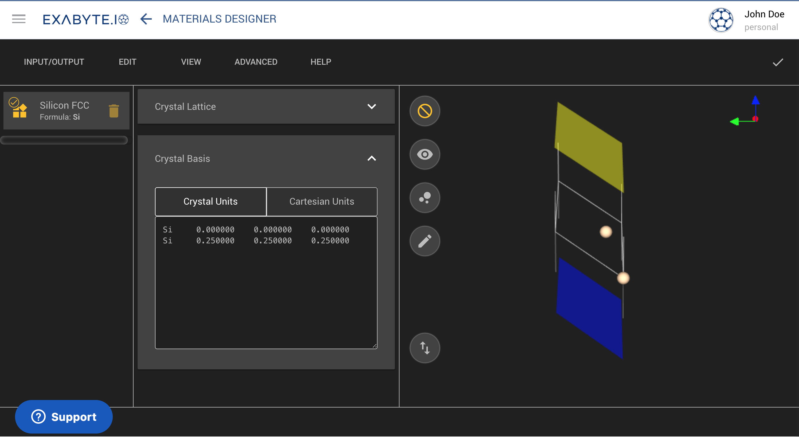
We apply the following conventions concerning the coloring of the boundary conditions, as they appear when visualized in the Materials Designer interface:
- yellow = vacuum
- blue = metal
Hence, the following example shown in the picture below corresponds to the "bc3" option mentioned previously, wherein the central slab is sandwiched between a layer of vacuum on top and another metallic medium underneath it.

Offset
Towards the right of the "Set Boundary Conditions" dialog, the user can set the numerical value for the offset, in Angstroms, defining the distance separating the edge of the slab system under consideration from its surroundings (defined via the above-mentioned boundary conditions options).
When boundary conditions other than periodic are chosen from the list of available options under the "Set Boundary Conditions" dialog, the reference system relative to which the slab is portrayed in the 3D editor interface changes from -L_z/2 to +L_z/2, instead of 0 to L_z as in the periodic case, where L_z is the total vertical thickness of the slab.
Apply Changes
Once the desired options have been entered within the "Set Boundary Conditions" dialog, click on the Submit button at the bottom of the dialog to implement the corresponding changes to the material under investigation.
Animations
In the following animation, we demonstrate how to switch between the four different available boundary condition options. The change in boundary conditions is reflected in the change of their respective coloring.
In this second animation below, we show the effect of changing the offset parameter described previously.